Background
Parallel manipulators are closed-loop kinematic chain mechanisms linked by several independent chains (Merlet, J. P. 2006). They have several advantages over serial manipulators such as accuracy and stiffness.
Because the chains are independent, each link does not have to support all subsequent links and can be lighter and smaller. The lower load and shorter link length reduce the (unmeasured) deformation in the system. The shorter kinematic chains also reduce the effect of deformation, actuator error and measurement error on the final end-effector position.
In a CNC machine
In the case of a 3-axis CNC machine, at least 2 axes will be in series. In the previous post it is the y and z-axis. Any deformation in the y-axis is magnified by the length of the z-axis. Any forces on the spindle are also multiplied by the z-axis.
Strength of Aluminum Extrusion
Before delving into parallel mechanisms, I need to determine if rigidity and accuracy are a problem in the current design. I will start with the frame.
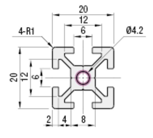
A design based on aluminum extrusions will depend largely on the strength of the fasteners. The standard 2020 extrusion has a wall thickness of 2 mm, and a overhang of 3 mm. T-nuts have widths from 6 – 15 mm. This imposes a limit on the bolt tension before it starts to shear off the extrusion wall. The bolt tension and coefficient of friction (between aluminum and steel, not high) further limits the ability of joints to resist sliding.
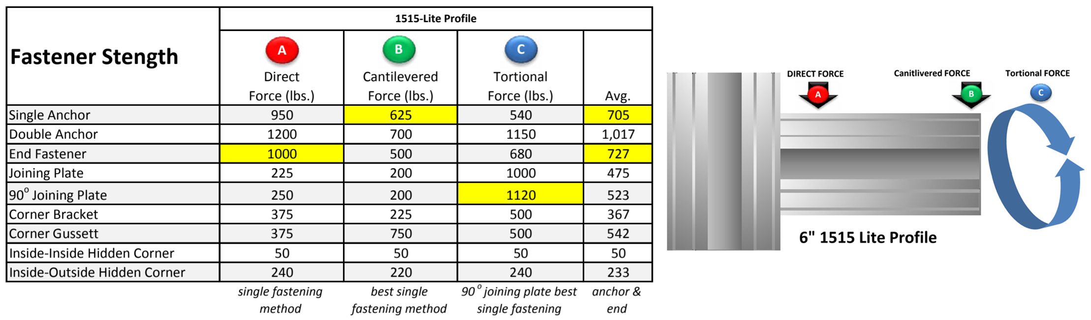
The layout of each joint also affects it’s strength. An extrusion that lays on top of another extrusion is much stronger than a joint that depends only on friction. The final option is to drill a hole, and bolt straight through the extrusion.
Deformation and Accuracy
Based on the FEA simulation, we saw a deflection of 0.8 – 1.6 mm with 10 N of force. A 500 W spindle cutting aluminum is capable of generating around 30 – 60 N of force on the frame (at higher depth of cut). The simulation also overestimated the fastener joints.
This means that in the current design, frame rigidity is a major bottleneck in cutting metal. One obvious solution is to change the material and/or method of construction. This would definitely increase the cost and amount of fabrication required.
I think that I will stick to aluminum extrusions because of its low cost, availability and the sheer convenience of being able to bolt a frame together. My hope is that a parallel mechanism design will overcome the material limitations.
Planar Parallel Mechanism
I think the most obvious starting point is to have a spindle mounted on a moving z-axis, and a planar parallel mechanism to replace an x-y table. One of the most common, and well-studied mechanisms is the 3-RPR robot.
The notation reads as: 3 independent legs with revolute – prismatic – revolute joints per leg. Each leg will have one active (driven) joint and two passive joints, most commonly the prismatic joint.
MATLAB Simulation (and visualization)
I started by writing a quick kinematic simulation in MATLAB. The base are denoted by blue circles, platform by red circles and legs by black lines. The grey circles show the maximum extension of each prismatic joint. There is no limit on the range for the revolute joints.
In subsequent posts I will explore
- The workspace
Which are the locations that can be reached - Singularities
Which are poses where the mechanism loses controllability and/or rigidity - Velocity, acceleration and static analysis
Used to determine the relation between joint velocities/force and end-effector velocity/force