Design Goal (Quantified)
After a few more weeks of research and reading up I have decided to use deflection at the spindle as my primary design goal. I plan to use depth of cut (DOC) + width of cut (WOC) to estimate the acceptable deflection.
Depth of Cut
DOC in aluminum ranges from 0.254mm/0.76mm/1.6mm (Shapeoko Wiki) to 2.54mm (Vince Fab) and 6.35mm (Shapeoko Forum).
Recommendations for the Tormach PCNC1100 is also 6.35mm (CNC Zone).
WOC is recommended to be between 0.1 - 0.5 of the endmill diameter.
Cutting Force
There is a chart on the Shapeoko forum that says that a 500W spindle will see a force of 4.5N (Shapeoko Forum). This seems extremely conservative.
Using the Kennametal milling calculator, and 0.02mm feed per tooth (FPT or chipload), and 220/150 m/min cutting speed (SFM)
| Endmill | DOC (mm) | WOC (mm) | RPM | MRR ($cm^3/min$) | Force (N) | Power (W) |
|---|---|---|---|---|---|---|
| 6mm 2F | 6 | 3 | 11671 | 84.0 | 108.8 | 710 |
| 6mm 2F | 4 | 3 | 11671 | 56.0 | 72.5 | 480 |
| 6mm 2F | 2.5 | 2.5 | 11671 | 29.6 | 36.3 | 230 |
| 6mm 2F | 6 | 0.6 | 11671 | 28.0 | 43.5 | 280 |
| 6mm 2F | 6 | 2 | 11937 | 57.3 | 108.8 | 490 |
| 6mm 2F | 6 | 0.4 | 11937 | 19.1 | 43.5 | 200 |
It is interesting that a 2.5mm/2.5mm DOC/WOC has a higher MRR at a lower cutting force compared to 6mm/0.6mm DOC/WOC.
Endmill Deflection
The CNCcookbook recommends a maximum deflection of 20% of chipload. At 0.02mm FPT, that is a deflection of $0.004$ mm. They also recommend 0.025mm as a general guideline.
HSMAdvisor calculates 0.01mm tool deflection at the most aggressive cut of 6mm DOC 3mm WOC.
The Sienci LongMill has 0.2mm in y at 29.4N (Youtube).
FEA Simulation
Worst Case (110N)
| X-Axis | Y-Axis |
|---|---|
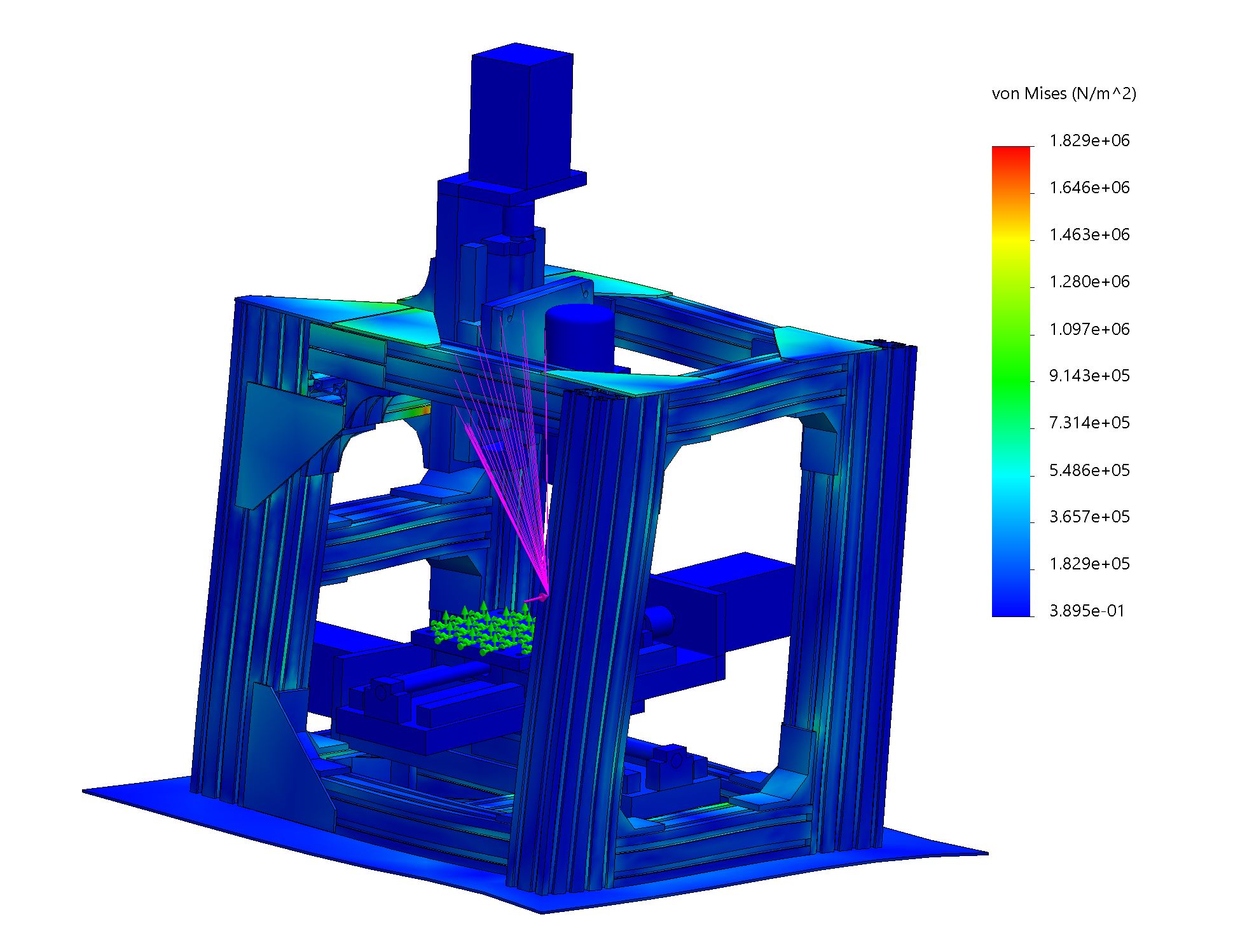 | 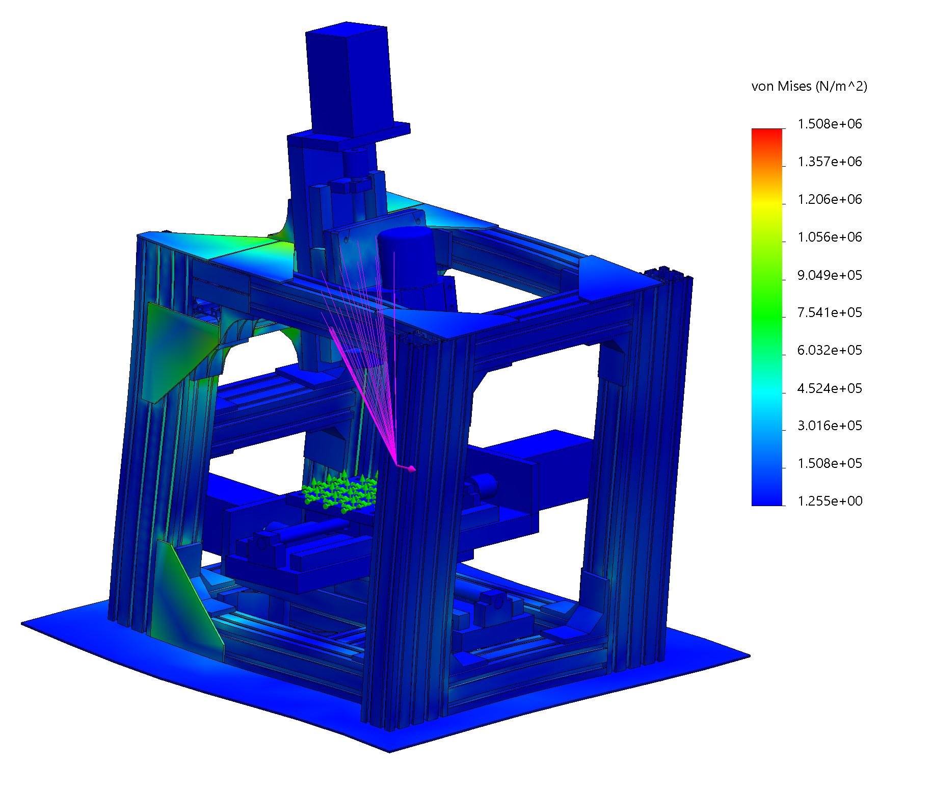 |
| X-axis: 0.020 mm | Y-axis: 0.018 mm |
Nominal (75N)
| X-Axis | Y-Axis |
|---|---|
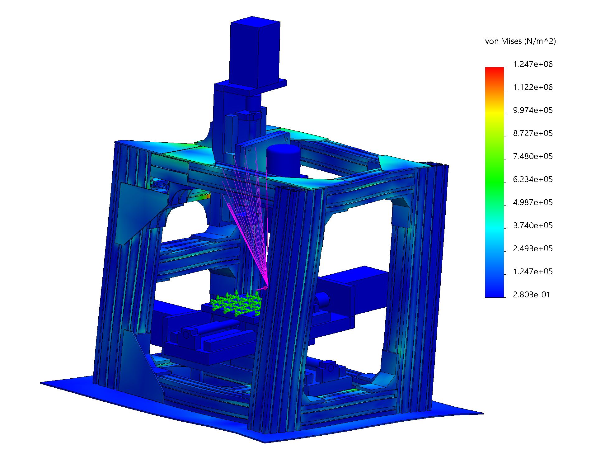 | 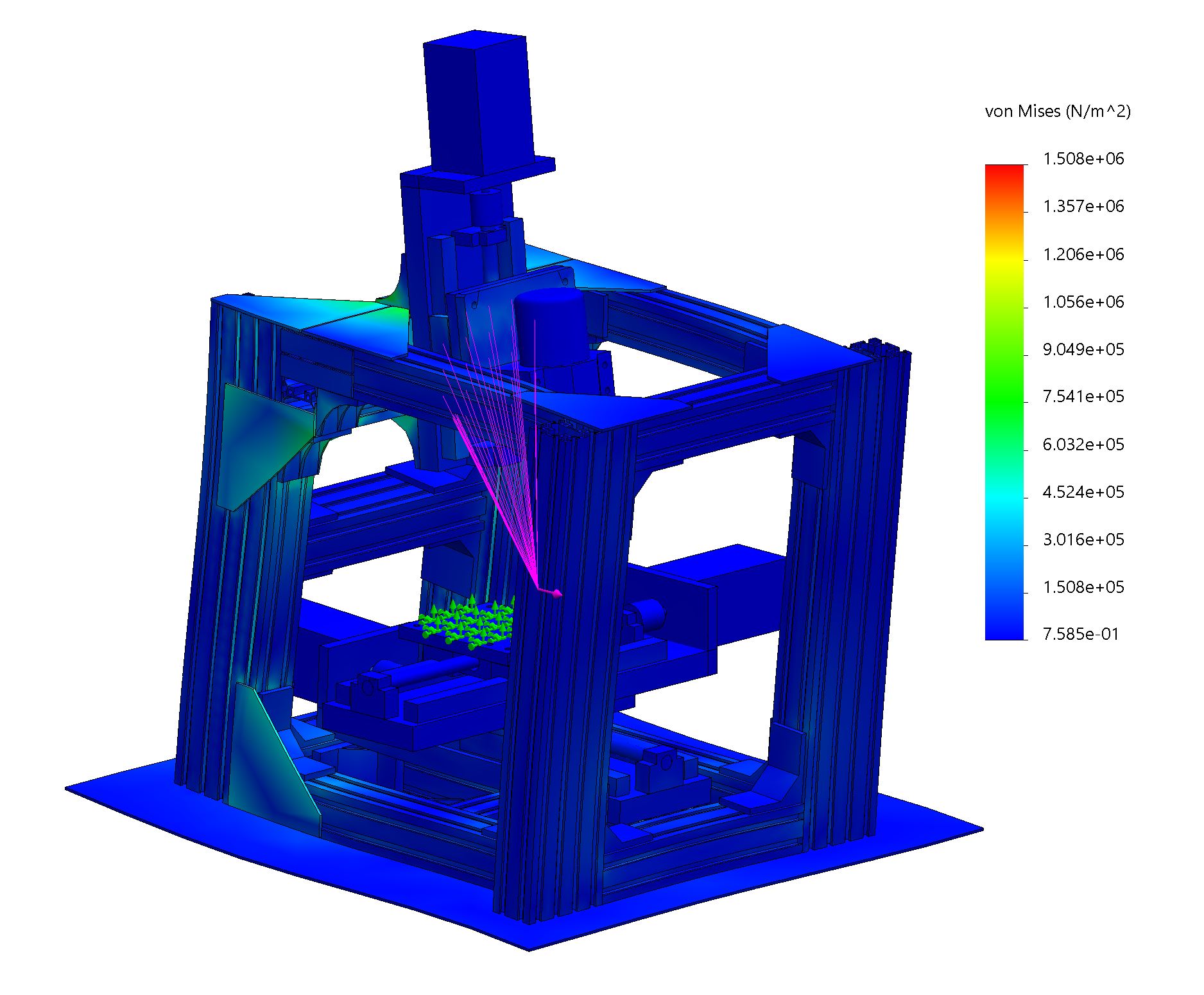 |
| X-axis: 0.013 mm | Y-axis: 0.013 mm |
The V2 has 0.013 – 0.020 mm on x and 0.013 – 0.018 mm on y. Because I’m using “bonded” contact sets, the actual deflection is likely to be 2-3$\times$ more than the simulation.
This means the deflection under nominal load (0.03 – 0.04 mm) will exceed the CNCcookbook guideline of 0.025 mm.