I stumbled on an excellent resource, Principles of Rapid Machine Design Bamberg, E. (2000). Principles of rapid machine design. It covers design and manufacturing principles, calculations and simulations, and experimental data.
Design Principles
Stiffness Budget
“One of the most important criteria is the effective stiffness of the tool/work piece interface, measured in force per unit deflection $N/\mu m$.” Bamberg states that values of 10 to 25 are desirable for machining.
The idea behind the stiffness budget is to assume each sub-assembly acts as a spring (of finite stiffness) and calculate the total stiffness from
$$ k_{tot} = \left( \sum_{i=1}^{n} \frac{1}{k_i} \right)^{-1} $$
The total stiffness of springs in series is given by the inverse of the sum of the reciprocals. Recursively apply this concept on each component in the sub-assembly until every sub-component is accounted for.
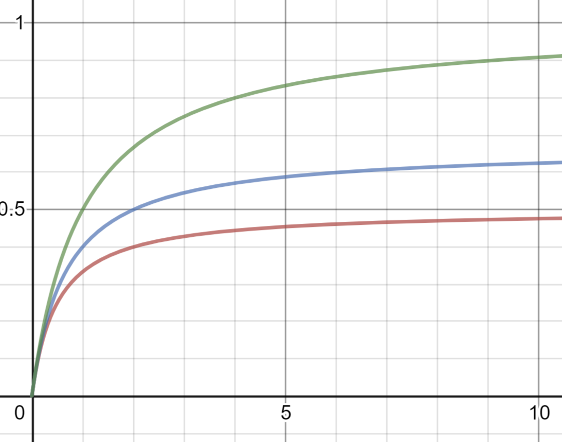
I graphed $k_{tot}$ as a function of $k_1$ for varying $k_2/k_3$. Because it’s the inverse sum of reciprocals
- One weak component can quickly bring stiffness to zero
- One exceptionally strong component has limited effect
Which means that the optimal design will be something like equal stiffness for every component?
FEA Modeling Techniques
Bearings
“A bearing block modeled from (…) steel or even aluminum will appear much stiffer than it actually is”. Bamberg offers two solutions:
- Modify the geometry to get accurate deflection
- Modify the material properties
He did this by calculating an equivalent Young’s modulus.
Manufacturing Principles
Aluminum profiles suffer from “excessive thermal expansion” and “limited strength of the joints” which limit it to “low force operations such as light machining”.
Bamberg raised a point that the structure a bearing rail is attached to has to be stiffer than the hardened steel rail. Otherwise the rail “would warp the structure rather than [be] straightened by it”.
These are potentially problematic. Putting aside thermal expansion and rail warping, I might be able to get stronger joints by making them bigger and accommodate multiple bolts.
Damping
Real machines are too complicated to be modeled as simple spring-mass systems. A common approach is loss factor $\eta$ , which is the ratio of average energy dissipated (per radian) to peak energy (per cycle).
Material Damping
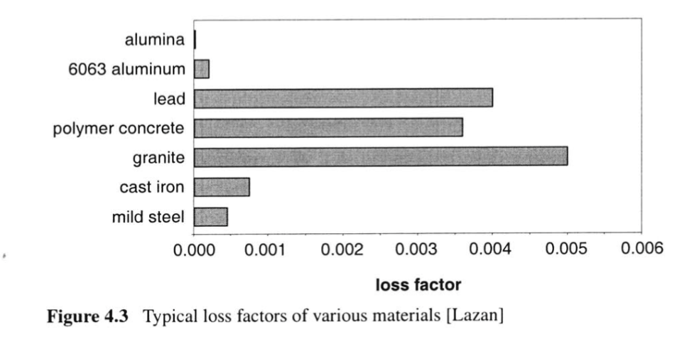
Principles of Rapid Machine Design
Aluminum has something like half the loss factor of mild steel, which might be a problem. But bolted joints provide damping because friction along the joint dissipates energy. “This type of damping is cumulative and therefore increases with the number of joints”.
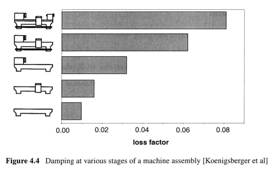
Principles of Rapid Machine Design
It is interesting that the joints and bearings provide 80 – 90% of the total damping. This means that using aluminum instead of steel is only a difference of 5 - 10%?
Something to investigate is the damping of a t-slot nut (normal and long variants) vs tapping a hole directly in the profile.
Conclusion
- Avoid any single point of low stiffness because of $k_{tot} = \left( \sum_{i=1}^{n} \frac{1}{k_i} \right)^{-1}$
- Joints are the weakest link in aluminum profile structures
- Aluminum has half the material damping of steel but
- 80 - 90% of total machine damping comes from bolts and bearings